-->

main-navbar

Saturday, December 21, 2013

The Action System

Been very busy during the college semester. Getting used to college, then trying to keep up, has left little room for this project. However, finals are now over and I have nearly a month off, so time to get some more stuff done.

This past week and in my spare time over the semester I have been working on the action system. In an earlier post I described the action system as a relationship between the user, the assembly, and the actions that the assembly is capable of executing through its modules. When I went to implement this, I discovered it would not be as simple as it first appeared. 

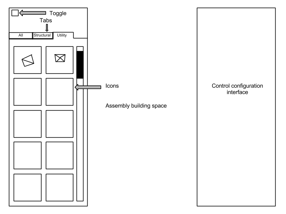
The action system was going to be broken into three parts: the easy to use simple logic system (this would allow direct designation of keys to specific actions), the logic/node editor (this would allow for very complex programming without the user writing any code), and the code editor (just like it sounds, you have to write code to program stuff). 

The first part, the easy to use logic system, was going to be implemented as fast and easy as possible while still allowing for expansion. Then later on, when more of the game functionality was added, the second part would be implemented, which would allow the complex node/logic editing in addition to the simple keybinding. The two are unfortunately inseparable. In order to implement the first part, the second part (or at least the underlying infrastructure) must exist first. 

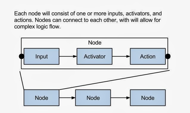
So this past week, and in my spare time over the semester, I have been working on the underlying infrastructure for the node editor. If you are familiar with programming, you can see how a node editor can be used to do logic. Each node in the editor will be broken into as many as three different parts: an input, an activator, and an action. The input is some sort of trigger or change, so you could use a variable change as well as a keyboard press as an input. Each input can be connected to one or more activators. As well, each activator can be connected to one or more inputs. The purpose of the activator is to handle the inputs and activate actions based on them. Each activator can also connect to one or more actions. The action is simply a link to a premade function within the code of a module. Anything passed to the action upon its activation, will also be sent to its target function. This target function can also be an input, so upon its activation it can trigger another activator. This depends on the actual code inside the action function, but it allows for some very complex behaviors.
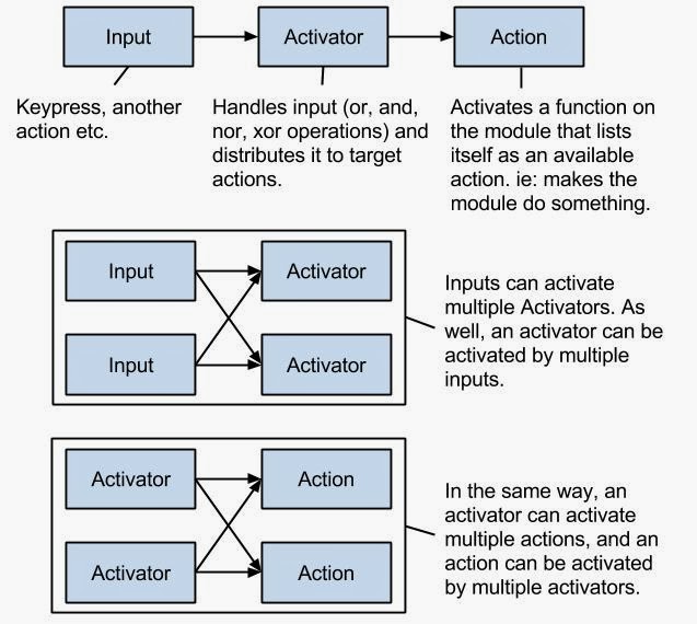
Each input/activator/action together makes a node. The user will be able to use these nodes to create the desired behavior.


The above system has been mostly implemented so far, with the exception of passing in or handling values, saving and loading the logic, and actual nodes. It works well for simple things like a keypress. One of the reasons that actions have to activate a target (predetermined) function on the module, instead actual in game functions that are required for the game to function is this: it limits the user to within the modules actual capabilities. ie: You cannot do something with the module unless it has been programmed to be able to do that. In this way you can controll the spacecraft however you like; your only limitation is its limitations. This makes sense, you wouldn't want someone changing, their max health, or making themselves indestructible, or other hacks.


Saturday, October 19, 2013

A word on Quaternions and doing complex rotations - Solution

In my older post on Quaternions, I described a problem, but failed to show the solution. Someone commented on that, so I felt inclined to do a full post describing the solution. This post is mostly code, and what it does, just a warning to those reading.

The problem was as follows:
How do you align the faces of two objects that are facing different directions on objects facing diferent directions?

Note the setup here; a side is one of the faces that are being oriented, the gameObject is the object the side is apart of. A side has its own custom class with information about it(where it is relative to the object, its orientation, its number of geometric sides, etc).

Step 1 - Create a rotation variable that you are going to manipulate. Assign it to the gameObjects current rotation:

var rot: Quaternion = gameObject.transform.rotation; 

Step 2 - Create a function that will manipulate the rotation to point it toward the target direction, how I did it is shown below:

function GetLookRot(side: Side, rotation: Quaternion){
var rot: Quaternion;
if(rotation == null) rot = gameObject.transform.rotation;
//assigns rotation for manipulation
else rot = rotation;
//the location of the side relative to the center of the 
//object, which is the same thing as a vector that starts 
//at 0,0,0 and passes through the location of the side.
var fromLocalDir: Vector3 = (location);
//target global location (of the target side)
var target: Vector3;
//this basically finds the vector that starts at the 
//target gameobjects center and passes through the target 
//sides center, all in global coordinates
target = (side.gameObject.transform.rotation
*(-side.location))
+gameObject.transform.position;
//takes the global vector described above and makes its 
//position local, its rotation is kept global.
var toGlobalDir: Vector3 = target 
- gameObject.transform.position;
//updates the first vector by modifying it from local 
//rotation to global rotation, while still keeping its 
//local position.
var fromGlobalDir: Vector3 = rot * fromLocalDir; 
//so now we have two vectors, the first points in the 
//current direction the side is pointing, and the second 
//points in the opposite direction the target side is 
//pointing, because we want the sides to face each other, 
//rather then simply point in the same direction.
//after that we get a rotation using unity's 
//FromToRotation to get a Quaternion that describes the 
//rotation of going from the first direction to the second 
//direction, this rotation is then combined with the 
//gameobjects current orientation, by multiplying, to get a 
//rotation that points the current side to be facing the 
//target side.
return Quaternion.FromToRotation(fromGlobalDir, toGlobalDir) 
* rot; 
}


Step 3 - The next function assumes that the sides are parallel, this takes them and aligns their sides. Because it handles rotations, the sides do not actually have to be parallel at yet, just the rotation you feed this function would have to put them parallel. This step is a bit more complicated....

 //returns a rotation that would rotate so the face is aligned 
//(ie: so all the vertexes of both sides are at same pos)
//with the target face, rotates along the normal axis of the 
//side. rotates current, or if given rotation, rotates that, 
//target rotation is given through the passed side
function GetAxisRot(side: Side, rotation: Quaternion){
var rot: Quaternion;
if(rotation == null) rot = gameObject.transform.rotation;
//assigns rotation for manipulation
else rot = rotation;
//def axis is a vector that originates at the center of the 
//side and passes through a vertex on the side. This is 
//used to represent the sides rotation around the y axis
//if the side was in a horizontal position
var direction: Vector3 = (rot*(defAxis));
//this is an array that will be used to hold the diferent
//possible vectors.
var targets: Vector3[] = new Vector3[side.polySides];
//sets the array of axies
for(i = 0; i < polySides; i++){
if (i == 0) targets[i] = side.gameObject.transform.rotation*(side.defAxis);
else{
targets[i] = side.gameObject.transform.rotation*(Quaternion.AngleAxis((360/side.polySides)*i, side.location) * (side.defAxis));
}
//shows each axis for visualization
Debug.DrawRay(side.gameObject.transform.position, targets[i], Color.red);
}
//shows each axis for visualization
Debug.DrawRay(gameObject.transform.position, direction, Color.red);
//the angle between the closest direction of available directions to target,     //and the target
var angle1: float = 360;
//the angle difernce between the direction that comes before the above and the   //target
var angle2: float = 360;
//the angle diference between target direction and current direction in +-       //degrees
var angle: float;
//assigns the above
var j: int;
for(i = 0; i < polySides; i++){
if (i == 0) j = polySides-1;
else j = i-1;
if(angle1 > Vector3.Angle(direction, targets[i])) {
angle1 = Vector3.Angle(direction, targets[i]); 
angle2 = Vector3.Angle(direction, targets[j]);
}
}
if(angle2 < 360/polySides) angle = -angle1;
else angle = angle1;
//applies final rotation
var finalRot: Quaternion = rot*(Quaternion.AngleAxis(angle, location));

return finalRot;
}

Step 4 - Once you have both functions you run them like this:

var rot: Quaternion = gameObject.transform.rotation; rot = GetLookRot(side, rot); rot = GetAxisRot(side, rot); return rot;

And that is how I did it, hopefully this can be of some use to someone :)

Saturday, August 24, 2013

Actions

Been really busy the past few weeks, so haven't had much to show for the time. With college classes about to start in two weeks the available time is only going to decrease. However, I did manage to create and partially implement the action system.

What this system does, is handle module actions. This will be integrated into how the AI runs, how the user controls and configures input, and will basically give a framework for handling each modules actions. For example, an engine type module would have actions for controlling the engine. The actions for such a module would be something like: Activate, Deactivate, Set Power, etc. So to get such an engine configured, you could assign say, the spacebar, to Activate the engine when pressed, and Deactivate the engine when released.

The system works by storing a list of the modules actions in the module itself. An action in this system is a custom class that has an activate function, and a constructor. The constructor assigns the target of the action, so when the action is "activated" it calls the targeted function. in addition the constructor assigns a description and a name for the action, so that the user knows exactly what the action does. All the actions are assigned at start of the runtime to their parent module, and made available to all objects that have access to the module. The assembly itself will be the main object activating these actions, and assigning inputs to activate specific actions. These inputs will be stored on the assembly itself so that individual sets of controls can be isolated. (ie: the user controls one assembly, and an ai controls another. Their actions dont activate each other because they are assigned to separate assemblies) Basically the assembly will act as the distribution hub for all of its modules actions. Eventually it will be possible to create custom actions which would set off multiple others, sort of like programming.

With this system, it would be possible to practically let the user program the ship as they would a robot. One of the cool things about this, is a user could create a control system and share it with others who just want to fly the ship, and skip the whole configuring aspect. Or even better, a user could create their own AI. These are some of the major end goals. However, for the moment a simple "this key/button activates this action" sort of thing will be created, until after some sort of release. More complex layers of possible programming will be possible later on.

There are still some fine details to work out, like accessing module variables, but for now I hope just to be able to get a ship that is completely configured by the user.

Saturday, August 3, 2013

Project Update

The demo video I released last week showed some of the features and capabilities of the editor. This past week I have been cleaning up code and adding a few more essential elements to the infrastructure of the program. I also made it possible to select one or more modules and delete the selected modules.

The last part was the most difficult; not so much the selection system as the deletion system. Normally deleting things would be very easy; but it this case it was not because of the assembly system. With the assembly system, each group of modules that are connected to each other form an assembly. The problem is; how do you handle the deletion of a module that is the only piece holding two halves of the assembly together? Somehow I had to get the assembly to update its internal list of which modules were a part of it and in addition I also had to split the assembly into two individual assemblies. This is what was the really tricky part.

Eventually I came up with an algorithm that worked; but it took a while. Basically the algorithm starts with the first module in the list of modules on the assembly. It takes this module and scans through all of the modules directly or indirectly connected to it. Then the assembly removes these modules from a copy of its internal module array, adds them to a list of groups of modules as a group, then repeats until no more modules are left in the copy of the internal list of modules. After this the first newly created group is assigned to the assembly and for every remaining group a new assembly is created and assigned the contents of that particular group.

Anyways that's what I spent most of the week working on. Next will be adding the input/module properties stuff. This will allow the engine to actually fire, and also will allow the user to make control systems so they can build and fly a ship. This will involve a gui on the right side of the screen as well as some serious infrastructure to handle it all.

Saturday, July 27, 2013

Editor Demo

Not just some text and a few pictures. Here is a basic version of the editor running. Its not ready for any kind of public testing yet, but I did make a video demo showing off a few of the things that are/almost done.
The demo shows a number of things:
-The basics of how building ships/assemblies will work
-The current GUI
-Saving and loading


As I add content to the program, I will periodically release a video demo. Once I think its bug-free and content rich enough, I will release a limited alpha.
Let me know what you think in the comments!

Saturday, July 20, 2013

What this project is about.

After reading through all my previous blog posts, I realized I still had yet to explain in depth what this project is!

There are two core goals for this project:
-To create an environment that can be used to create and test complex dynamic AI's.
-To create a game environment that gives the user the most freedom in terms of control over their own abilities in the game.

In order for the first of these goals to be met, there needs to be a well developed core infrastructure to the game. In other words, the environment has to be tried and true before development of an AI can begin.

The second goal, is a bit more ambiguous. To explain it a little bit clearer: what I want to do, is allow the user to create and experience what it is like building and designing assemblies for use in space. My goal is to have it to such a level, that you could design your own missile, carry it with your ship, and fire it. My goal is to allow the user to create a ship that can do things it was never meant to do, like disassembling mid flight to avoid an anti matter missile, or split your ship into two and control both ships as if they were one. My goal is to allow the user to create their own AI ship if they so desire. These are the things I want to allow the user to do, and in a (somewhat) realistic fashion. Your ship wont fly because it just does; it will fly because you installed antimatter reactors directly next to thrust vectored engines. It will shoot because you attached some huge capacitors next to your customized high power feed laser. I would like it even possible to have multiple people controlling the same ship, star treck style.

These goals are a bit ambitious, you may say: "okay that's cool, but how are you going to do all that?" and I say: "one step at a time".

The first steps involved concept art (mostly in my graph paper notebook) and background planning; ie how to allow the user to do these things.

I came up with idea of using "modules" to build the ship out of. Modules are great because they are stand alone, can be used in complex configurations, and they can allow complex behaviors. As of now they all connect with triangular sides, but the code is in place for any kind of polygon to be used as a connection side; as long as it connects to a side of the same type.

The different kinds of modules that could be used:
-Engines
-Power Generators
-Laser Weapons
-Shield Generators
-Shield Emitters
And anything else that ends up being cool

I also plan on each module to have customization options, like the ability to balance how much power goes into the wavelength of the laser, and how much into the amount of photons fired. The goal is to have as much customization as possible while still keeping things balanced. Also, i would like to make it possible to place things on top of the modules, that are not actually modules. More like accessories. This would let you coat everything with armor, or attach antenna and other sensors in various places on the ship.

So that's the goal of this project. Now, anyone have an idea for a name? I originally called it polyhedra wars because many of the modules I had in place resembled polyhedra (ie octahedrons, tetrahedrons etc). But modules are not all going to look that way, many are going to have their "insides" shown. Anyway, let me know what you think in the comments.

Concept ship design, its hard to draw polyhedra by hand!

Thursday, July 18, 2013

Unity GUI - Graphics

There are two parts to making a GUI in unity; the graphics and the programming. These two parts mix a bit, but when I say graphics here, I mean the GUI skin. Unity's GUI system is a bit tricky to work with, and making your own customized skin can be a bit daunting. I realized that the default unity GUI wouldn't work, not even for testing, because all its controls are translucent and very dark. Most of the time in space, there are really dark colors. The default unity GUI tends to become nearly invisible against this kind of backdrop, and that's when I realized that I would need to make my own. If you want to see the results, skip to the bottom.

Note: before you go ahead and make a full blown GUI skin; make sure none of the ones on the asset store will do. There are a lot of decent skins for $5, and even some nice free ones. I neglected to do this, and as a result spent a lot of time making my own skin when it may not have been necessary, though it was an interesting experience.

Once you have come to the conclusion that the unity skin, the free skins, and the non-free skins are not options, then that's when you make your own. Before you even get started though, draw it out on paper, preferably graph paper. You do this so that when you finish making the skin, you don't go back and realize that 30+ images need to be redone. This also helps prevent redoing a simple image 20 times to get it just  right. Once you got a good idea of your skin down on paper, you can get started with the computer stuff.

One thing that needs to be taken into account, is how unity handles images. I spent 2 hours trying to figure out why my "crisp clean images" were all blurry before I realized the import setting : "texture type" of each image had to be set to GUI. The other settings can also be important depending on your image type. Its not usually to hard to figure out settings that work, the important part is making sure texture type is set to GUI.


The filter mode handles how the image is stretched. Point just scales the pixel, biliniar is good for textures with gradients, triliniar does something with mippixels. All this info is available in detail at the Unity Texture 2D documentation page found here.
After all the import settings are taken care of, the next step is to setup a test script that shows off all the GUI elements that you plan on using. I followed the tutorial here, which has a nice little script for this purpose, though it doesn't use all the elements (I made this; it has all the elements. The code is a bit messy but its only for visual testing). The tutorial also shows how unity handles stretching of textures at different places to make small textures seamlessly scaleable. The tutorial doesn't cover everything but its good for an introduction. After finishing it, its not that hard to just follow the same pattern of making images with the right borders, then changing the border setting in the skin to make it fit right.

Some elements do not follow the same pattern though and need a bit more work to get working. Notably is the toggle. When you make the toggle, make sure that you leave a section of pixels to the right for whatever you want stretched beneath the toggle text. Usually this is just blank alpha.

<-- That bit of white to the right is alpha used by the toggle text.

When making a skin, its also good to have the default textures available for reference, they can be downloaded from the asset store for free, and also on the unity forums here.

For scroll bar buttons, you need to make sure the fixed width and height are set above zero; otherwise they will not show up in your skin. Only do this if you actually want them to show up.


After finishing the last GUI texture, its a bit satisfying to see a nice GUI when you are done. I will not say its easy, but it can be rewarding to make your own custom skin. Below are some pics:


I ended up making two versions, a translucent version, and a solid version. The translucent skin looks like a better fit, so I will likely go with that one. Making the skin translucent isn't that hard, especially for flat styled skins. You simply take each solid texture, copy the solid color, adjust the alpha value to about half (I used 125 on 0-255 scale), use a paint bucket tool on replace mode where you took the color from, then save the image. If by any chance you don't want to make your own, and you really like this skin, its on the asset store here.

That about concludes making a unity GUI skin, next comes the programming. This was more of a list of common pitfalls, or at least ones I fell into, then a GUI tutorial. There are lots of tutorials on youtube and in many other places, so don't just go by this if you decide to make your own skin.

Saturday, July 13, 2013

Planning a project and parsing texts

In my experience it is always best to work on the part of the project you are least confident in your ability to finish. The reason being that you do not want to finish everything else and find that you are, indeed, incapable of completing that particular part. While working on all my projects I have kept this in mind. There are other benefits as well; if you are capable of finishing that part, and you do finish it, then you got the hardest part done first. In addition, this helps keep you encouraged throughout the projects completion because every step brings you much closer. It could be argued that it makes it harder because starting with the hardest part is discouraging. But it will have to be faced at one point or another anyway.

This way of working on projects is best used when you already have experience, because otherwise your project is mostly a learning experience and may not be finished. Working on the toughest part of a project without at least some experience, can be much more daunting, and also much more discouraging.

The reason I bring this up, is because working on my project by using this strategy has lead to some interesting decisions. For instance, the next part of my project was going to involve the gui, so I planned it out by drawing what I wanted it to look like when it was done, and how I wanted it to function. Next I planned the lower level stuff, like how It was going to have that functionality in the first place. And finally, when all that planning was done, I looked at what was the most important and what was most difficult and worked on the next step that most balanced these two.

The gui that I planned was entirely for the ship editor aspect of the game. This aspect is what I consider the most important because it is what makes my game unique, and as a result is what I want the most polished. Since everything else is in place it is also the last step before there can be another release, so it makes sense to work on the ship editor part next.

The gui's layout has parts you can select to build with on the left, and on the right of the screen is the interface for configuring controls or activation keys. Now, because the editor is such an integral part of the game, it will be able to be accessed during flight, allowing real time editing of the ship. The user will be able to switch back and forth between the editor and the flight modes even during a battle, though during a battle would be dangerous.

At default the windows will pop out when the user hovers the mouse at that edge of the window. This makes it easy to access what you need and get the display out of the way quickly. In addition, there will be a toggle that when toggled, will keep the window out even when the mouse is not hovering over the window. Each icon represents a module that can be placed on the ship, or as I like to call it, assembly; because it may not necessarily be a ship that is being built. The list of modules also has a list of tabs at the top, to help categorize the modules.

This gui is nice and all, but I also needed as convenient a place as possible to store the available modules in the unity project. I also wanted something that was easily changeable and even moddable in the future. At the time I decided this, my unity project was in dire need of "housecleaning", it had many unorganized files and resources that were not even being used. I figured it best to start a new project and import what I needed as I went. After this was done, I got to the modding/module organization system.

The system works like this: in the project and build, there will be a folder with a list of .module files. The files can be in sub-folders and really in any order as long as they are in the modules folder. When the game is started, all these module files will be parsed for their contents. Each module file contains a list of all the aspects of the module, and in the future, references to texture and mesh files. In the meantime prefabs already in the built project will be referenced. Any of the .module files can be edited by a text editor, or new ones can be added. Parsing these files appeared the most difficult, as a result, that is what I worked on next.

First I planned out the syntax of each module, then I did a ton of research on the String class in the msdn libraries. For fellow unity developers; msdn is the place to go for all lower level code references. I also looked up how to parse a string in google; this provided a few handy results like: reading a text file line by line, and one method of text parsing. These weren't the only results, but they were the most useful. Anyway, how you parse a file mostly depends on the layout and syntax of it. So for my .module file I decided to read each line one at a time using the method described in the first link. Then I split each line along the = sign using String.Split. Properties on the left side were used to describe where to put the value described on the left. In some cases there were values that were compound. Take for example the custom Side type, it has a position, rotation, name, and variable for the number of sides(polygon sides, not Side type objects). (This is used to describe how to handle the connection sides in the game, ie what connects two objects together) For this type, I declared Side, followed by { and all the variables followed by a }. The text parser, when it read "side" would go into a corutine, reading all the lines until it got to the }. Then the parser would resume its normal operations.

The main task of the parser is to produce a list of modules that the gui can list as icons and the user can place as modules. In addition, only modules loaded this way are used to load a save game, or a saved assembly.

Now...time for that gui.


Saturday, July 6, 2013

A word on Quaternions and doing complex rotations

Its been some time since I last made a post here. Not for lack of working, but rather of lack of something to post. For the past several months I have been working quite a bit in Unity3d on Quaternions.

I will talk about that below; the first point is that I haven't made many posts here. To keep whoever bothers following this blog on my project interested and up to date, I will write a blog post (to the best of my ability; post is still not guaranteed) every Saturday with some info on what has been worked on/ updated etc. And for those that even that is not enough, I plan on making a twitter account with daily updates on progress. Now as a warning to those who wish to read on, below is a rant/very long post on quaternions which some may find fascinating and others boring.

Quaternions are what unity uses to describe rotations. Unity also has something called eulerangles, which  has the more easily interpreted 0-360 notation that we are used to using for rotations. The main reason unity uses quaternions as the underlying way of calculating an objects rotation though, is because quaternions don't suffer from something called gimbal lock. The major disadvantage of quaternions, is that their representation is very complex, so much so in fact that quaternions are best simply referred to as variables instead of their individual values. For a mathematical explanation of quaternions, here is a good explanation that might give you a little bit of an idea of what the values actually mean. However, the explanation went a bit over my head, and the variable method of representation is sufficient.

My problem with quaternions started when I tried to do something a bit complex, and all at once. The idea was to add a hook function for rotating one side of a module to be facing another side of another module.  So I setup something simple for selecting the sides that needed to face each other. I set it up so all that was needed was the new rotation to rotate too.

Each object stores its side as a rotation and position relative too the center of the module it is on. This greatly reduces lag from object creation and destruction compared to when I had an entire GameObject representing each side, but it added a complication; instead of rotating one module to be facing another, I had to rotate one rotation of a modules side to be facing another rotation of another modules side.

In the below example side one is selected to rotate facing side 3, and the goal was to rotate it so it looked like side 2; both sides plains are parallel, and the corners of the modules are aligned.
My first solution to get a rotation that would rotate in this way was to try rotating all at once, and i came up with this line of code:  

gameObject.transform.rotation*Quaternion.Euler(orbit))*(Quaternion.Inverse(Quaternion.Euler(side.orbit+Vector3(0, 0, 180)))
note: orbit is the sides relative rotation in euler angles to the module it is on. Quaternion.Euler converts it to a quaternion.

This line is the result from hours of trial and error and was by no means the most efficient time I spent. However, it still worked to provide the desired rotation. I am honestly still not entirely sure why it works, but it does, so I was fine with it. That is, until I tried to rotate the resulting rotation. 

At some point I realized I needed to rotate the returned rotation, the reason being that if you connect modules into a "loop" where there are connections connecting in a loop pattern, the assembly will destroy itself. In the example below the red shows the "loop" that would be created. The blue shows the corner of the side that would rotate toward the other corner of the other triangle if the above line of code was used to provide the target rotation.
If a joint is added with this rotation as the target, then the assembly literally flies apart. So as a solution I attempted to use the angle axis function to rotate the resulting rotation in a way that would return the correct target rotation. Only problem was, using the angle axis function seriously messed up the rotation; it rotated on some arbitrary axis as a result of the original rotation calculations. I spent a long time attempting to rectify this, but nothing worked and I was forced to attempt a different approach.

I was back to square one and I did what I should have done from the start: rotate in steps. Eventually I came up with a rotation that would align the faces of the two objects, which was really a modified LookAt function. From there I was able to use angle axis to rotate the previous rotation to the final rotation. This resulted in the desired rotation of the modules.

To sum up: Do quaternion rotations in steps; it will save you a LOT of trouble, and will certainly not cause you to learn a million things about quaternions you never needed to know.
note: the last part of the above sentence is not guaranteed not to occur. 

Edit: The details (with the actual code) on how this was solved can be found here.


Monday, May 6, 2013

Module System partially implimented +Status Update and Future plans

The module system has been partially implemented. Currently, via this system, objects can be added, respond dynamically and as well their states can be partially saved.

However, I am still working on the loading system.
Once the module loading system is done I plan on making the join system reworked.

As the old joint system currently is, it is hard to save which joints are connected to what. And the old system just doesn't cut it when it comes to what I want to be done in this program, so this is how the new system will work:

-Individual joint components will not be saved as they have been before, rather instead each module will save which object it was connected to, then when all the modules are loaded, they will individually add joints between themselves "automagically".

-Instead of using the unity based joint component as the main interface for all joint based things, a joint class will be created that both objects that are connected by the joint can access. Before, only the object that had the actual joint component on it could access this data without a bunch of workarounds. This way it will standardize how each joint is accessed with no need for the additional complexity.

-This joint class will contain a variety of useful functions on things to do to the join, and simplify code outside of the joint itself.

Once the joint system is finished, tried and tested, I will begin working on the new GUI system. Unity's current GUI system is a mess, requiring lots of code to do very little; I am currently planning to replace it with  NGUI. This will enable a much better and user friendly GUI then currently exists.

And as a final note, there is a way to embed unity web-players into blog posts, so on the next update the game will be playable on a separate page on my blog.

Anyway, that's the deal for now, Signing out,
-Patrick

Friday, April 5, 2013

My new laptop came in about a week ago. Now I can start really working on this project. During the time I didn't have a laptop up I came up with a better way of handling the code as well as some new ideas that will make it simpler, allow for more complexity, and make programming easier. My main focus is going to be implementing this new system.

How the new system will work: 

Instead of everything being called components, and ships, there will be 3 different types of objects.

-The first is the Module. This is going to take the place of the components, so all the modules will be the building blocks of your project.


-The second is the Assembly. The assembly, in a nut shell, is an assembly of Modules, that together, do something. Everything that combines two or more Modules will be considered an assembly. An assembly will also only save the tree structure of the ship. In other words, when you save an assembly, instead of it saving the positions of all the components, it will save which components are connected to what. This will make it simpler code and build wise.


-The third is the Accessory. The accessory is like a modification for the Modules. These go on the outside of modules, and allow things like armor plating, shield generators, laser turrets, etc. Basically an accessory is anything connecting to a Module that can only connect to one Module at a time.


Comments, thoughts, questions, ideas? Fire away!